Precision Adhesive Transfer Component Repair | BK Industrial Coatings
Applied Surface Repair & Coating Development

Precision Adhesive Transfer Component Repair

Two-repair validation of a documented carbon-fiber smoothing bar restoration process.

When a damaged production contact surface cannot be treated as a normal coating job, the repair has to be diagnosed, designed, measured, documented, and repeatable.

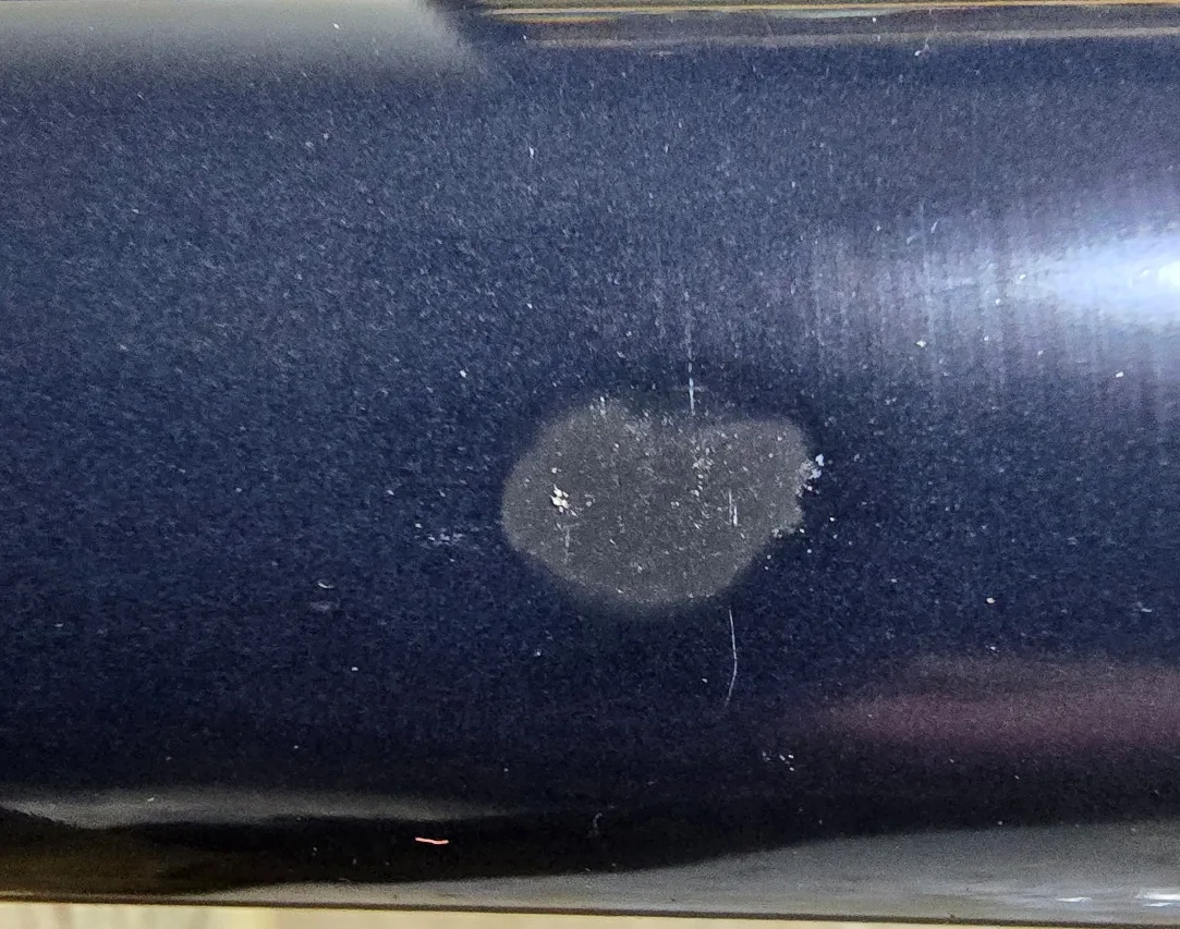
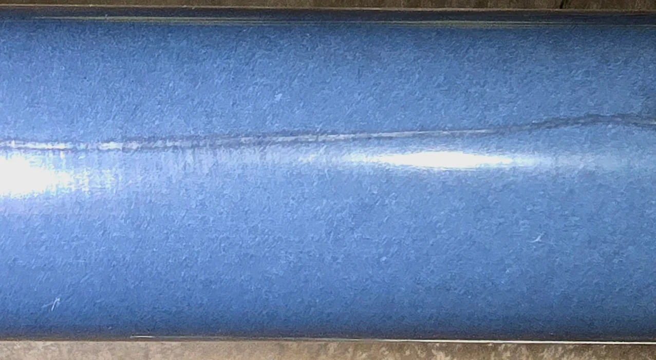
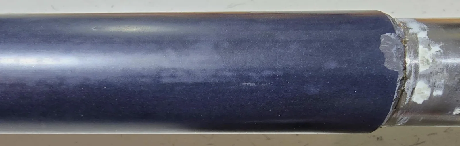
Restored production contact surface on a carbon-fiber smoothing bar
Restored precision adhesive-transfer component after coating/substrate restoration and dimensional finishing.
  • 2separate repairs
  • 11mapped defects
  • 4Repair 1 defects
  • 7Repair 2 defects
  • 0.29 to 0.01 mmDF6 roundness deviation
  • 0.22 to 0.06 mmDF1 roundness deviation
  • 42.00 mmnominal diameter target
  • 41.95 to 42.05 mmtypical post-repair range

Technical executive summary

BKIC repaired two damaged carbon-fiber smoothing bars used in precision adhesive-transfer work. This was not a standard coating job. The damage involved coating breach, exposed substrate, surface defects, and dimensional concerns on a production contact surface.

The first repair established the method: identify the surface behavior, map the defects, rebuild the damaged areas, preserve contact geometry, apply the final coating system, and document the result.

The second repair repeated that method across a separate bar with seven mapped defects and stronger dimensional proof, including a DF6 roundness correction from 0.29 mm to 0.01 mm and a DF1 correction from 0.22 mm to 0.06 mm.

Client and manufacturer names are withheld. The technical record, measurements, images, and repair logic are shown from BKIC project documentation.

Material identificationCoating behavior was tested before repair decisions were made.
Coating/substrate restorationCarbon fiber exposure shifted the job from appearance work to surface repair.
Dimensional restorationDiameter and roundness checks supported the repair outcome.
Technical documentationPhotos, defect IDs, measurements, and process notes were organized into reviewable evidence.

Project evidence

The project record shows the repair as a measured process, not a cosmetic improvement. Defect tables, component figures, material observations, repair-method notes, and post-repair measurements document how the work was evaluated and repeated.

Repair 1 measurement table

Four mapped defects established the process

DefectPositionMeasured conditionRepair relevance
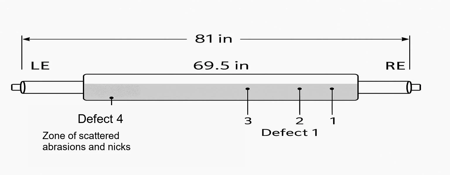
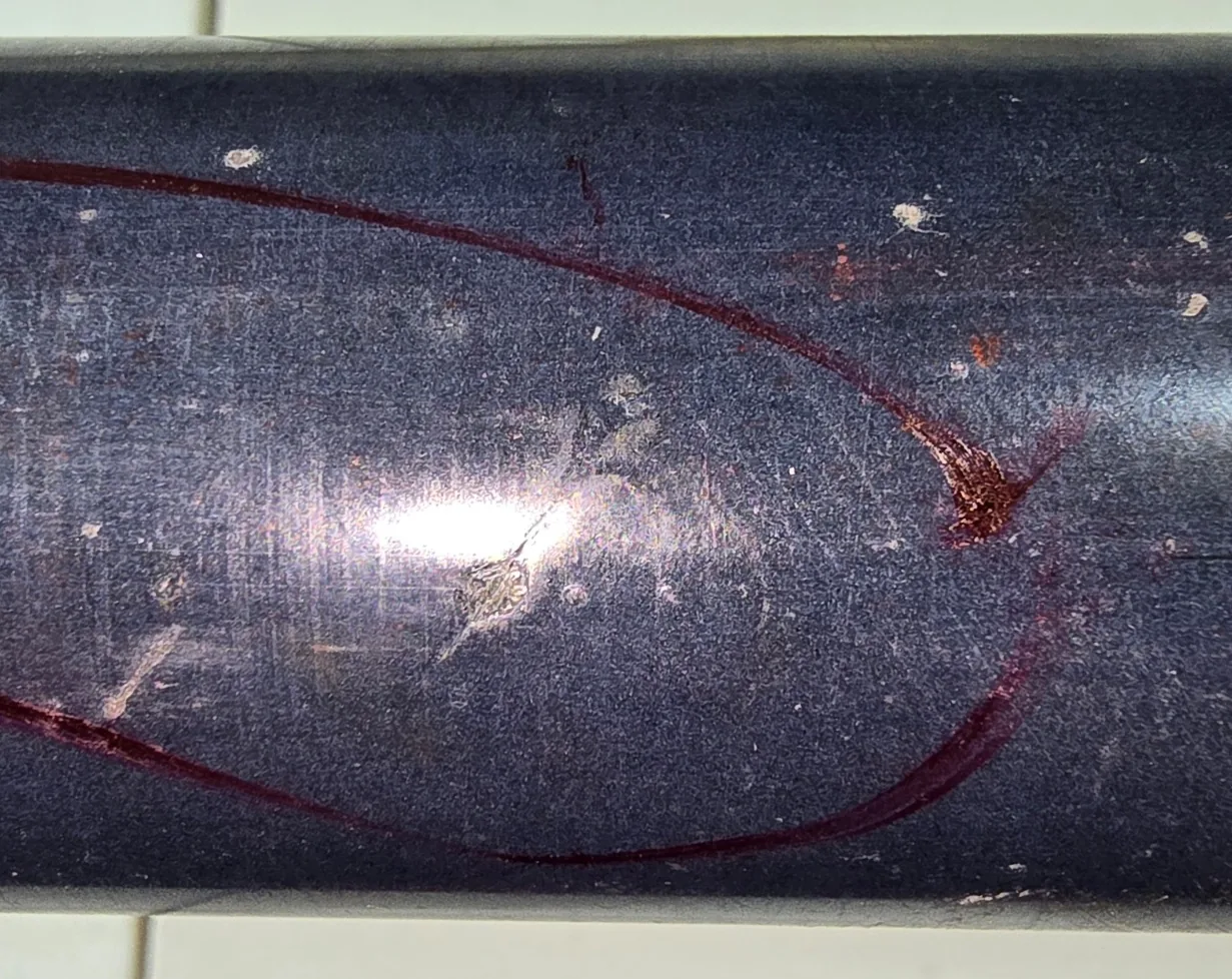
Defect 148.07 mm from RE18.20 mm x 8.31 mm, approx. 0.15 mm depthFull breach into carbon fiber
Defect 2454 mm from RE5.70 mm x 9.47 mm, approx. 0.05 mm depthGouge-style depression
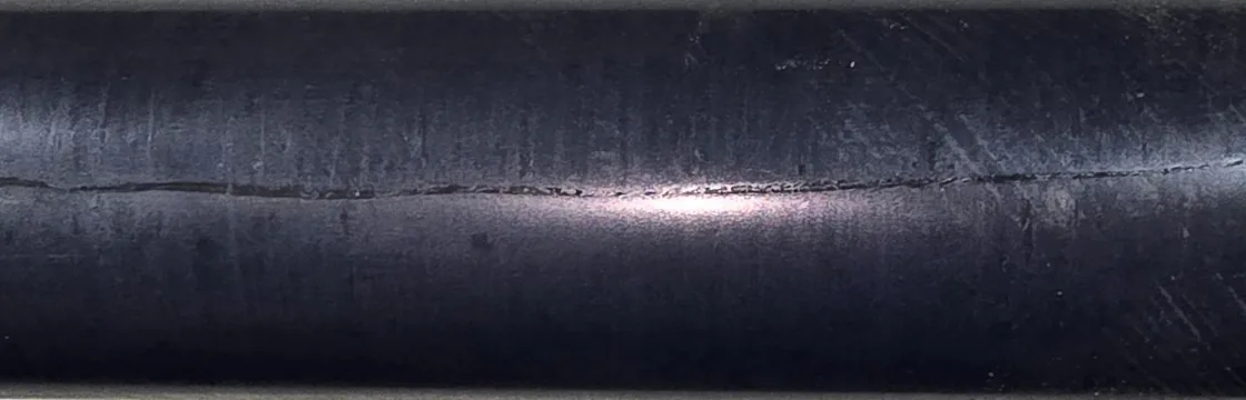
Defect 3533 mm from REPuncture with 6-inch hairline crackCrack and breach stabilization
Defect 4Beginning at LEScattered abrasion zoneSurface abrasions and adhesive residue blend
Repair 1 defect location sketch for a carbon-fiber smoothing bar
Repair 1 defect location sketchProject figure showing LE/RE orientation and mapped defect positions.

Repair 1 material identification and coating behavior

Coating behavior was treated as evidence

The coating resisted IPA, acetone, and MEK. Polishing did not produce softening, gumming, or material breakdown.

The observed behavior suggested a high-durometer epoxy-type coating, potentially UV-cured or thermally baked, on an OEM carbon-fiber smoothing bar.

Repair 1 repair methodology

Repair material selection was tied to surface function

PC-7 was selected for adhesion, hardness, sandability, and compatibility with the ceramic topcoat.

A skim coat bridged microtexture differences, filled microvoids, reduced edge transition risk, and helped preserve geometry before final coating.

Repair 1 key outcomes

Process established without compromising bar geometry

Repair 1 stabilized and resurfaced four major defect areas while maintaining dimensional consistency within approximately 0.02 mm across the working zone.

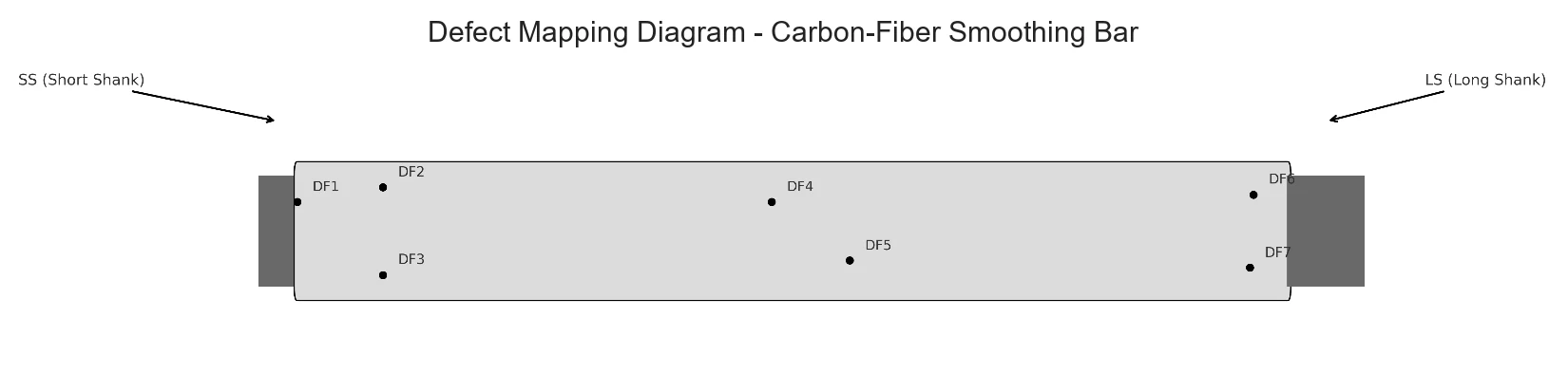
Repair 2 defect mapping diagram for DF1 through DF7 on a carbon-fiber smoothing bar
Repair 2 defect mapping diagramProject figure showing DF1 through DF7 mapped across the second bar.

Repair 2 roundness table

Roundness deviation before and after repair

DefectPre-repair deviationPost-repair deviationResult
DF10.22 mm0.06 mmImproved by 0.16 mm
DF20.02 mm0.02 mmMaintained
DF30.01 mm0.03 mmWithin working tolerance band
DF40.02 mm0.03 mmWithin working tolerance band
DF50.04 mm0.01 mmImproved by 0.03 mm
DF60.29 mm0.01 mmLargest correction
DF70.05 mm0.05 mmMaintained

Repair 2 diameter deviation analysis

Post-repair readings returned toward 42.00 mm

Most post-repair X/Y measurements returned toward the 42.00 mm nominal diameter, generally within 41.95 mm to 42.05 mm.

Most post-repair roundness deviations were reduced to about +/-0.03 mm of axis alignment.

Repair 2 repeat validation

The same repair logic repeated on a separate bar

Repair 2 repeated the methodology, materials, and coating system established in Repair 1 across seven mapped defects, including the largest correction at DF6 and the DF1 short-shank repair zone.

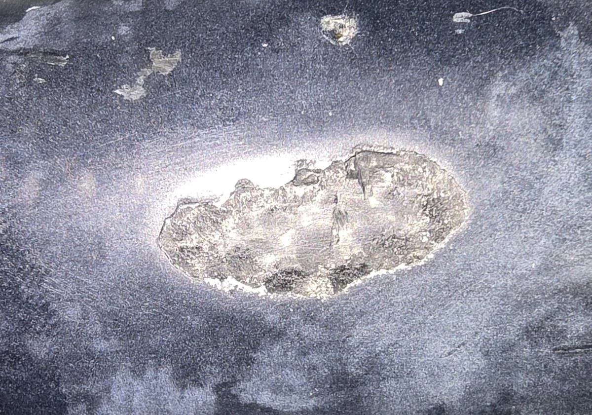
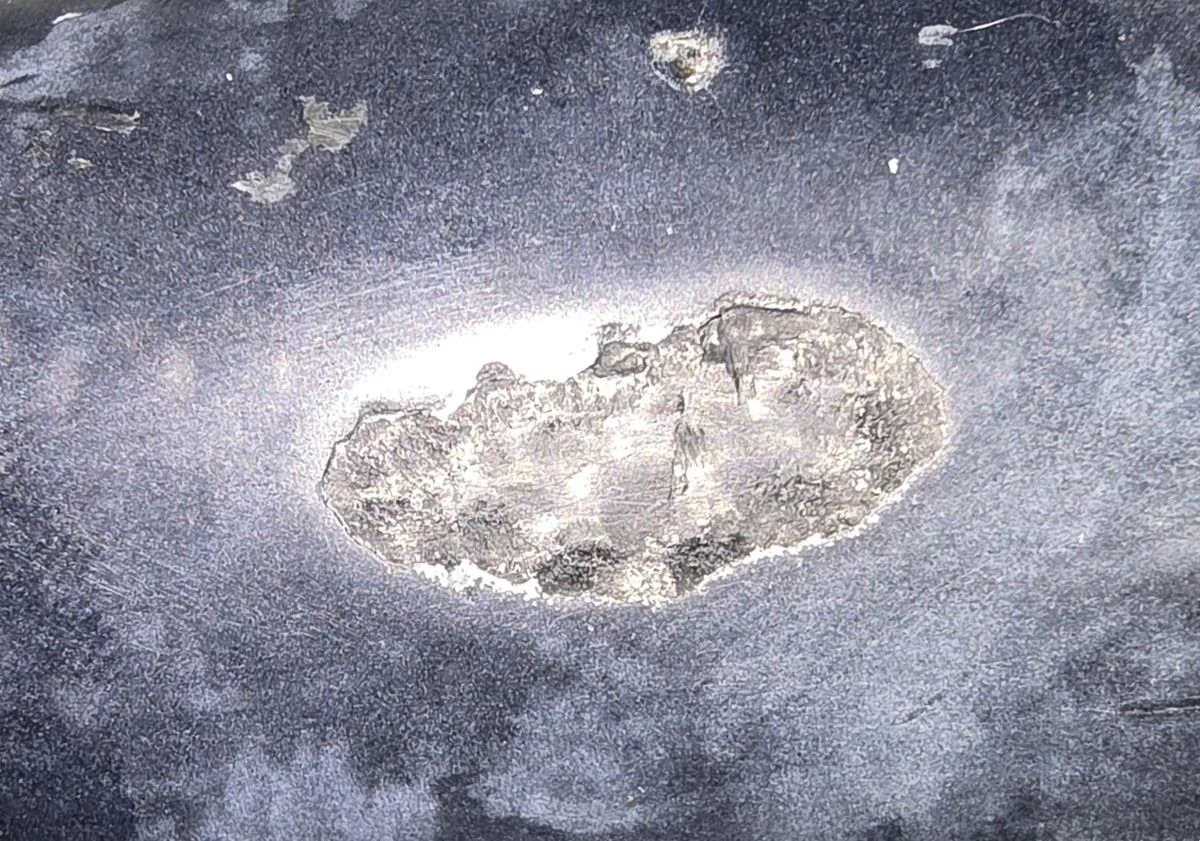
Coating breach and exposed carbon fiber on a production contact surface
Substrate exposureCarbon fiber exposure changed the repair from cosmetic coating work to coating/substrate restoration.

Material identification and repair reasoning

BKIC evaluated the component as a surface-behavior problem before selecting the repair path. The repair material, skim coat, sanding sequence, and ceramic topcoat had to work together without creating a high spot on the production contact surface.

Solvent resistanceThe coating resisted IPA, acetone, and MEK during material identification.
Polishing behaviorPolishing did not soften, gum, or break down the coating.
Coating inferenceThe behavior suggested a high-durometer epoxy-type coating, potentially UV-cured or thermally baked.
Repair materialPC-7 was selected for adhesion, hardness, sandability, and compatibility with ceramic topcoat.
Skim coatThe skim coat bridged microtexture differences, filled microvoids, and reduced edge transition risk.
Final coatingThe ceramic coating was applied in two stages after controlled sanding and dimensional shaping.

Defect atlas

Eleven mapped defects across two repairs gave BKIC a repeatable repair record instead of a single isolated outcome.

Repair 1: four mapped defects

  1. Defect 1Full breach into carbon fiber, 48.07 mm from RE, approx. 18.20 mm x 8.31 mm, approx. 0.15 mm depth.
  2. Defect 2Gouge-style depression, 454 mm from RE, approx. 5.70 mm x 9.47 mm, approx. 0.05 mm depth.
  3. Defect 3Puncture with 6-inch hairline crack, 533 mm from RE.
  4. Defect 4Surface abrasions and adhesive residue blend beginning at LE.

Repair 2: seven mapped defects

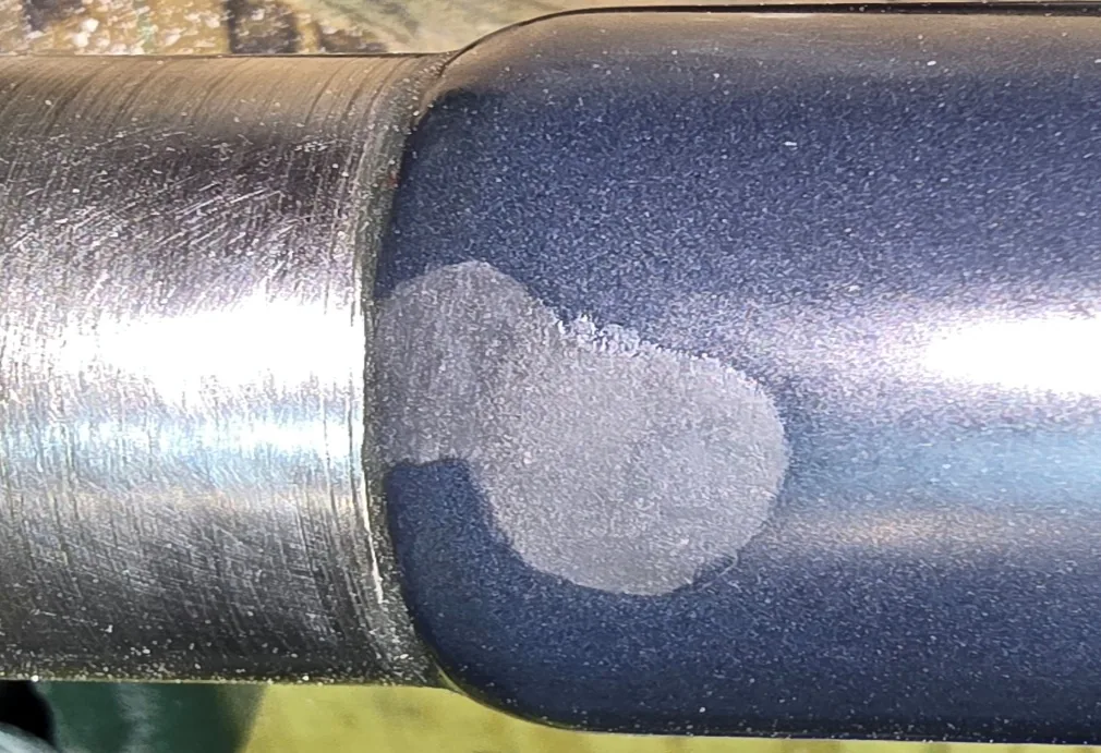
  1. DF1Full carbon fiber exposure near short shank, 0.20 mm depth, 16.95 mm width.
  2. DF2Localized impact site with chip/checking.
  3. DF3Tactile nicks.
  4. DF4Long scratch zone, 7.5 inches wide.
  5. DF5Surface chip with minor cracking.
  6. DF6Elevated chip cluster, 0.29 mm deviation, largest correction.
  7. DF7Impact mark with exposed carbon fiber.

Measurement dashboard

The measurement record focuses on defect count, roundness improvement, nominal diameter recovery, and selected interval readings from Repair 2.

Defect count by repair

Repair 14
Repair 27

Eleven mapped defects across both reports.

DF6 roundness correction

Before0.29 mm
After0.01 mm

DF6 was the largest measured correction.

DF1 roundness correction

Before0.22 mm
After0.06 mm

DF1 improved at the short-shank repair zone.

Nominal diameter band

41.95 42.00 mm target 42.05

Most post-repair measurements clustered in this range.

Post-repair readings clustered around nominal

42.00 0 in 5 10 25 30 35 40 45 Post X Post Y

Selected 5-inch interval readings

IntervalPre X/YPost X/YPre dev.Post dev.
0 in41.93 / 41.7141.96 / 41.900.220.06
5 in41.86 / 41.8641.98 / 41.970.000.01
10 in41.89 / 41.8942.01 / 41.980.000.03
25 in41.91 / 41.9142.01 / 42.010.000.00
30 in41.93 / 41.9342.05 / 42.020.000.03
35 in41.92 / 41.9442.03 / 42.020.020.01
40 in41.96 / 41.9442.02 / 42.010.020.01
45 in41.96 / 41.9642.04 / 42.040.000.00

Repair process timeline

The method was documented as measured repair logic, not appearance-only coating work.

  1. Intake and defect review

    Review the component surface, visible damage, and contact-surface function.

  2. Material behavior testing

    Evaluate coating response to solvent exposure and polishing behavior.

  3. Defect mapping

    Assign defect IDs, positions, damage types, and measurement relevance.

  4. Substrate exposure assessment

    Separate cosmetic defects from coating breach and carbon fiber exposure.

  5. Mechanical preparation

    Prepare unstable edges and damaged areas before fill or skim coat work.

  6. Targeted fill

    Use selected repair material where the surface needed rebuilding.

  7. Full-surface skim coat

    Bridge microtexture differences and reduce edge-transition risk.

  8. Controlled wet sanding

    Shape the restored surface toward nominal diameter and contact geometry.

  9. Ceramic coating application

    Apply final coating in two stages after surface restoration.

  10. Dimensional verification

    Compare post-repair readings against roundness and diameter targets.

  11. Report documentation

    Package photos, measurements, methodology, and results for review.

Two-repair validation

Repair 1 established the process. Repair 2 repeated the same methodology, materials, and coating system.

Repair 1 stabilized and resurfaced four major defect areas without compromising bar geometry and maintained dimensional consistency within approximately 0.02 mm across the working zone.

Repair 2 applied the process to a separate carbon-fiber smoothing bar with seven mapped defects. The dimensional proof was stronger: DF6 moved from 0.29 mm to 0.01 mm roundness deviation, and DF1 moved from 0.22 mm to 0.06 mm.

Repair 1

Process established

Material logic, defect mapping, fill strategy, skim coat work, controlled sanding, ceramic coating, and measurement documentation.

Repair 2

Repeat repair

Same repair logic repeated across a second bar with seven mapped defects and post-repair roundness proof.

What this proves about BKIC

BK Industrial Coatings can take on surface problems that do not fit a normal service category. When coating condition, substrate behavior, contact geometry, repair material selection, and documentation all matter, BKIC can evaluate the problem and build a measured repair path.

This does not mean every damaged component should be repaired. It means BKIC can determine whether a documented repair approach is realistic, then produce the evidence needed to review the outcome.

Measured repair logicRepair decisions were tied to defect mapping, surface condition, and dimensional checks.
Coating/substrate compatibilityMaterial behavior and final coating compatibility were considered together.
Dimensional restorationRoundness and diameter readings supported the repair record.
Technical documentationThe work generated photos, measurements, method notes, and report excerpts suitable for review.

Industrial applications

BKIC can evaluate whether a documented repair path is realistic for surface problems where coating, wear, corrosion, geometry, or production contact behavior affects service life.

Coated production contact surfaces Carbon-fiber or composite process components Adhesive-transfer and lamination-related surfaces Manufacturing equipment surfaces Fleet/equipment components affected by coating, corrosion, wear, or surface condition Specialty coating repair and documentation projects

Bring BKIC a surface problem that does not fit a normal coating, polishing, or replacement category.

Send photos, component material if known, failure mode, surface function, dimensional requirements, and what the component contacts in service.